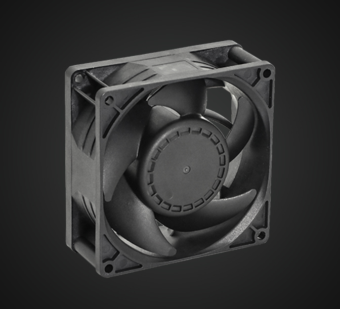
DZ09238-F04

类 型:双滚珠
风 量:90.57~123.50CFM
尺 寸:80x80x38mm
额定电压:12V
重 量:153.0g
DZ08038-F06
类 型:双滚珠
风 量:90.57~123.50CFM
尺 寸:80x80x38mm
额定电压:12V
重 量:153.0g
DZ12038-F05
类 型:双滚珠
风 量:90.57~123.50CFM
尺 寸:80x80x38mm
额定电压:12V
重 量:153.0g
DA04056-F01
类 型:双滚珠
风 量:90.57~123.50CFM
尺 寸:80x80x38mm
额定电压:12V
重 量:153.0g


The principle of thyristor, what are the classification and main parameters of thyristor?
2022-06-14 14:33:29
Click:
“
SCR for short, is a high-power electrical component, also known as thyristor. It has the advantages of small size, high efficiency, good stability and reliable work. In the automatic control system, i
”
SCR for short, is a high-power electrical component, also known as thyristor. It has the advantages of small size, high efficiency, good stability and reliable work. In the automatic control system, it can be used as a high-power drive device to realize the control of high-power equipment with low-power controls. Its appearance has brought semiconductor technology from the field of weak current to the field of strong current, and has become a component that is eagerly used in industry, agriculture, transportation, military scientific research, as well as commercial and civil electrical appliances.
1. Working principle diagram of thyristor
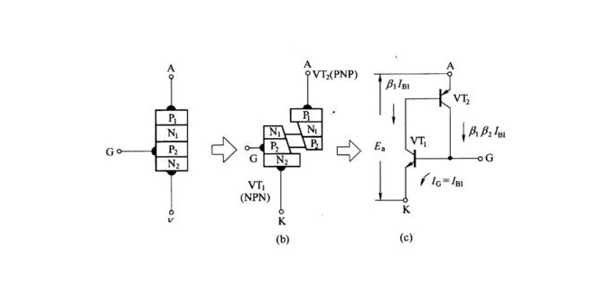
The thyristor has three poles - anode (A), cathode (K) and control pole (G). The core is a four-layer structure composed of overlapping P-type conductors and N-type conductors. There are three PN junctions. It is very different in structure from the silicon rectifier diode with only one PN junction. The introduction of the four-layer structure of the thyristor and the introduction of the control electrode has laid the foundation for its excellent control characteristics of "controlling the big with the small".
In the application of thyristor, as long as a small current or voltage is applied to the control electrode, a large anode current or voltage can be controlled. At present, thyristor components with current capacity of several hundred amperes or even thousands of amperes can be manufactured. Generally, the thyristor below 5 amperes is called low-power thyristor, and the thyristor above 50 amperes is called high-power thyristor.
2. What are the functions of thyristor?
One of the functions of thyristor is controlled rectification, which is also the most basic and most important role of thyristor. The well-known diode rectifier circuit can only complete the function of rectification, and does not realize controllability. Once the diode is replaced by a thyristor, a controllable rectifier circuit is formed. In a most basic single-phase half-wave controlled rectifier circuit, when the sinusoidal AC voltage is in the positive half cycle, only when a trigger pulse is applied to the control electrode, the thyristor will be triggered and turned on, and there will be voltage output on the load, so The average value of the output voltage on the load can be further adjusted by changing the arrival time of the trigger pulse on the control electrode to achieve the effect of controllable rectification.
The second function of thyristor is to use it as a non-contact switch, which is often used in automation equipment instead of general-purpose relays. It has the characteristics of no noise and long life.
The third role of the thyristor is to play the role of switching and voltage regulation. It is often used in AC circuits. Because of its different trigger times, the current passing through it is only a part of its AC cycle, and the voltage passing through it is only the full voltage. part of the output voltage, thus playing a role in regulating the output voltage.
3. SCR classification
The thyristor is divided into two types: one-way thyristor and two-way thyristor. Triac is also called triac, or TRIAC for short. A triac is structurally equivalent to two unidirectional thyristors connected in reverse, and this thyristor has a bidirectional conduction function. Its on-off state is determined by the control electrode G. Adding a positive pulse (or negative pulse) to the gate G can make it conduct forward (or reverse) direction. The advantage of this device is that the control circuit is simple and there is no reverse withstand voltage problem, so it is especially suitable for use as an AC non-contact switch.
4. What are the main parameters of thyristor?
1. Peak Forward Blocking Voltage (VPFU)
Refers to the peak value of the forward voltage that can be repeatedly applied to the device under the condition of open gate and forward blocking. This voltage is specified as 80% of the forward breakover voltage value.
2. Peak Reverse Blocking Voltage (VPRU)
It refers to the peak value of the reverse voltage that can be repeatedly applied to the device with the gate open and the rated junction temperature. This voltage is specified as 80% of the maximum reverse test voltage value.
3. Rated average forward current (IF)
When the ambient temperature is +40C, the device is turned on (standard heat dissipation conditions) and can continuously pass the average value of the sine half-wave current of the power frequency (that is, the power frequency supplied by the power supply network. Generally, 50Hz or 60Hz, 50Hz in my country).
4. Average Forward Voltage Drop (UF)
The average value of the voltage drop between the anode and the cathode when the device is supplied with the rated average forward current under specified conditions.
5. Holding current (IH)
The minimum forward current necessary for the device to remain on when the gate is open.
6. Gate trigger current (Ig)
The minimum direct current of the gate electrode necessary to make the thyristor fully conduct when a DC voltage of 6V is applied between the anode and the cathode.
Author:
Dongguan Merry Electronic co., LTD


TEL
+86-769-21 665206

JENNIE@MERRYELC.COM

WEB
WWW.MERRYELC.COM

Dongguan Merry Electronic CO.,LTD
Dongguan Merry Electronic CO., LTD Was established in year of 2013,Mainly engaged in design, development and sales semiconductors...

点击右上角
分享给朋友吧
Copyright ©2022 Dongguan Merry Electronic CO.,LTD All Rights Reserved